ACOUSTIC NOISE
- Fundamentals
- Fan Selection Hints
- Acoustic Noise Control
- How to Make Quiet Fans
Acoustic Noise Fundamentals
- Sound is a change in pressure with respect to atmosphere
- Noise is unwanted sound
- Speed of sound in air is 1,130 ft/sec (340 m/sec)
- Wavelength y=c/f
- where: c = speed of sound
- f = frequency of sound (cycles/sec)
- Normal range of hearing is 20 Hz to 10,000 Hz
- Most sensitive range is 1,000 Hz to 4,000 Hz
Acoustic Noise Measurement
Decibels - Logarithmic scale - 0 to 150
0 dB = threshold of hearing
20 dB = Rustling leaves
50 dB = Average Two-Person Conv
70 dB = Average Street Noise
80 dB = Vacuum Cleaner
110 dB = Subway Train
130 dB = Threshold of Feeling (pain)
140 dB = Jet Aircraft
Adding decibels:
dB1+dB2+…+dBn=10log(((10)dB1/10)+((10)dB2/10)+…+((10)dBn/10))
Examples:
1 - Two equal decibel values (I.e. two identical fans) add to produce a 3 dB increase.
86 + 86 = 89 dB
100 + 100 = 103 dB
2- Two decibel values differing by 6 dB add to produce a 1 dB increase
86 + 80 = 87 dB
100 + 94 = 101 dB
Acoustic Noise Fundamentals
- Noise Analysis
- Microphone - Measures pressure fluctuations
- Analyzer - Takes amplified pressure fluctuations and processes the information into useful information.
- Narrowband analysis
- Octave Band Analysis
- Weighted Scales
dBa, dBb, dBc.
- Octave Bands
- 1/3 and Full Octave bands
- Typical curves are full octave bands with center frequencies from 63 to 8,000 Hz
- 1/3 Octave band measurement simply divide each octave band into thirds

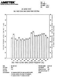
Typical Full Octave Band Typical 1/3 Octave Band
How to Make Quiet Fans
- Vary # of blades to shift blade passing frequency
- Modify trailing edge of blade to control vortex shedding noise
- Vary # of stationary vanes in vaneaxial fans
- Proper material selection
- Proper balancing techniques
- High grade bearing
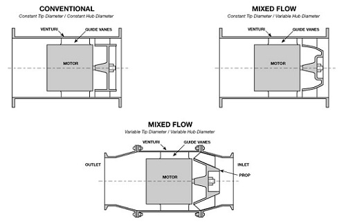
- Control speed of air through the fan by changes in geometry
Air Mover Selection Hints
- Run as slow as possible
- Pick a fan that will operate at peak efficiency
- Be aware of blade passing freq and harmonics
- Blade Passing Freq = NZ/60 (Hz)
where: N = # of blades
Z = rotational frequency in RPM
- Fundamental noise freq must not equal mounting structure natural freq.
- limit line of sight to prop / rotor
- Acoustic damping foam
- Filters can damp noise (EMI + Air Filters)
- Mechanical isolation
- Control air velocity in system. The lower the better.
- Keep sharp objects away from prop / rotor. This will create another fundamental frequency
- Put fan as far away from noise critical area as possible
Acoustic Noise Control
- Limit line of sight to rotor
- Acoustic dampening foam
- Filters can dampen noise (EMI + Air Filters)
- Mechanical isolation
- Control air velocity in system. The lower the better.
- Keep sharp objects away from rotor. This will create another fundamental frequency
- Put fan as far away from noise critical area as possible
STRUCTUREBORNE NOISE
- Most SBN at rotational frequency + harmonics
- Smaller spikes at blade passing frequencies + harmonics
- Noise Control
- Vibration isolators
- Rotor balance
- Stiffness of structure
- High grade bearings
- Mil-Std-740
Structure Borne Noise (SBN)
Due to the increased emphasis on systems which are difficult to detect with sonar equipment, primarily for undersea platforms, there has been a great deal of research dedicated to reducing noise which is "structure borne" or transmitted through solid media, such as mountings and cabinet frames. This type of noise, while related, is often significantly different from acoustical "airborne noise". There are many causes of SBN, some of which are similar to acoustical noise. One factor is the balance of the rotating component of the unit, however, there are several other factors which affect many other frequency ranges of the total signature. SBN is measured by attaching an accelerometer to the frame of the fan and creating a spectrum plot with an FFT analyzer or similar equipment. By analyzing the results of such a test and comparing them to readings taken when the fan is mounted in a system it is possible to determine what frequencies are causing a negative impact on system performance. A combination of fan modifications to change its characteristic signature and isolation or dampening techniques have proven highly successful in helping meet rigorous specifications.
SOUND PRESSURE VS. SOUND POWER
Sound Pressure Level (SPL) - Measurement of the pressure fluctuations referenced to the threshold of audibility. Level is a function of microphone distance from noise source
Sound Power Level (PWL) - Measurement of the sound intensity from the source. Is independent of distance (similar to heat and light energy measurements)
For single point noise source (I.e. fans)
SPL = PWL - 10 (at distance of 3 ft)
Sound Power and Sound Pressure
Almost all sound measuring instruments respond to sound pressure. Human ears and microphones are both pressure sensitive devices.
SPL = 10 log X (p2 / pref2), dB (eq.23)
SPL = 20 log X (p2 / pref), dB (eq.24)
where p = rms sound pressure, N/m2 Pref = reference sound pressure, N/m2
The reference sound pressure for air is 2 X 10⁻⁵ N/m2 which is also the threshold pressure of audibility.
Unlike sound pressure, which is measured at a point, sound power is an integrated value of the sound intensity around a source. Sound power, like heat or light energy, cannot be measured directly, and indirect approaches have to be adopted.
The sound power level is based on a reference power.
PWL = 10 log (W / Wref) (eq.25)
where W = acoustic power in watt
Wref = the reference acoustic power = 10-12 watt.
There are various techniques and environments used in the calculating and measuring sound power of a source. Once the sound power output of a source is known, it is frequently necessary to convert the power to an expected sound pressure level at some distance away from the source In a free field, i.e. with no reflecting surfaces, sound pressure decreases in accordance with the inverse square law. In the case of a non-directional source, the radiation is uniform in all directions. However, for a source with directionality the radiation is non-uniform. Therefore, before making a conversion from sound power to sound pressure, account must be made of the directionality. The directivity factor Q is defined as the ratio of sound pressure squared at a given distance and direction from the source, to the sound pressure squared that would be produced at the same location by the same source radiating uniformly.
To convert sound power level to sound pressure level, the following equation is used:
SPL = PWL + 10 log ( Q / 4pr2) + R, dB (eq.26a)
where PWL = sound power lever, watt, re 10-12 watt
r = distance in meter
R = room constant
Q = directivity factor
If r is in feet:
SPL = PWL + 10 log (Q/4pr2) + (4/R) + 10 dB (eq. 26b)
In this equation, Q/4pr2 is the effect of the direct field, and 4/R is the contribution of the reverberant field. In a free field, with soft floors, i.e. non-reflecting, there is no reverberant field and the above equation simplifies to:
SPL = PWL - 20 log r-.05, dB (eq. 27)
where r is in feet and Q = 1
However, in most cases the floor is hard and hence reflecting and here:
SPL = PWL - 20 log r + 2.5 dB
where r is in feet and Q = 2
In calculation of the sound power level from the sound pressure level, a space-averaging technique is used. The space-averaging can be either a hemispherical area (equation 28) or over a spherical area (equation 27) depending upon the nature of the measurement environment. Generally, most rooms in which sound pressure level measurements are made have a fairly hard floor and walls that are reflective. In such cases, the term involving the room constant, which is based on the wall absorption coefficient and room volume, must also be considered.
Sound Intensity and Intensity Level
Intensity level, like sound power level, is difficult to measure and is found indirectly from the rms sound pressure. It is given by:
I = (p2 / pc) watt/m2 (eq. 28)
where p = rms sound pressure
p = density of air
c = speed of sound in air.
This represents the energy passing through a unit area.
Intensity level is also expressed in decibels relative to a reference intensity.
Intensity level L1 = log10 ( I / Iref) (eq. 29)
Where Iref = reference intensity, 10-12 watt/m2In many practical cases, sound intensity and pressure are identical numerically when the proper units for each are used, i.e. watt/m2 for intensity, and micro-newton/m2 for pressure level.
NOISE ANALYSIS
- Microphone - Measures pressure fluctuations
- Analyzer - Takes amplified pressure fluctuations and processes the information into useful information.
- Narrowband analysis
- Octave Band Analysis
- Weighted Scales
- dBA, dBB, dBC
- Acoustic Measuring Environments
- Anechoic Chamber
- Semi-Anechoic Chamber
- Reverberant Room
Noise Rating-Acoustic
A number of noise ratings are currently used in specifying the noise of a product. Most of these ratings are based on people's response to noise. Each human activity is influenced differently by noise. The choice of these ratings depends upon the circumstances under which they are to be used.
Preferred Speech Interference Level (PSIL)
This is a single number rating and is the arithmetic average of SPL of the noise in the three octave bands with center frequencies 500, 1000, and 2000 Hz. This number is a good guide to the interfering effect of noise on speech communication. Hence, this rating is commonly used for noise control on office equipment where normal voice communication is very essential without shouting.
Loudness and Loudness Level
Considerable work has been done correlating loudness as perceived by humans with the level and frequency content of sound. There are, however, no instruments which measure either loudness or loudness level. Loudness levels were first obtained using a panel of human listeners. To determine the loudness, a reference sound of known level at 1000Hz was chosen, and a listening jury compared the sound with this reference sound. The unit of loudness is sones. Loudness level, measured in phons is equal to the SPL of a pure tone at 1000 Hz that sounds equally loud. Thus, a sound that is judged to be as loud as a 40 dB 1000 Hz tone has a loudness level of 40 phons or a loudness of one sone, since one sone by definition is equivalent to 40 phons. Sones and phons are related by the equation:
S = 2(p-40/10)
(eq. 31)
If noise is ten times as loud as the sound of one sone, then its loudness would be 10 sones. Normally a doubling of loudness corresponds to a change of approximately 10 phons.
Noise Criteria or Preferred Noise Criteria (PNC)
These curves combine the effects of loudness and speech interference level. The preferred noise criteria curves are a recent modification of the old NC curves. In order to use PNC ratings, noise measurements have to be made in full octaves, although some form of PNC does exist for 1/3 octave-band measurements. Though a PNC value is a single number, it represents a curve in the frequency spectrum. The PNC value of any sound source specifies the maximum noise level permissible in each octave band for the corresponding PNC curve. As an example, a noise rating of PNC 50 means that the noise level (SPL) is not to exceed the PNC 50 curve in all the eight octave bands. Preferred noise criteria ratings are the most widely used of all ratings.
"A" Weighted Sound Level, dB(A)
This is the sound pressure level measured directly by a sound level meter equipped with a filtering system which de-emphasizes the low frequency (below 500 Hz) portion of the audible spectrum and also the very high end (10,000 Hz and above). This system could be said to represent the human ear's response to noise. Since this rating system is very easy to obtain and also correlates well with the other ratings mentioned, it is very widely used. This rating is mostly used by the law enforcing agencies.
All these ratings, though widely accepted, are only single number values and give no information as to the frequency content of the noise.